0 99 Counter Circuit Diagram 50++ Images Result
0 99 Counter Circuit Diagram. Because its counting sequence is 0,1,2,3,4,5,6,7,8,9. If pin 3 is connected to the ground we will get a blank display on 7 segment output.
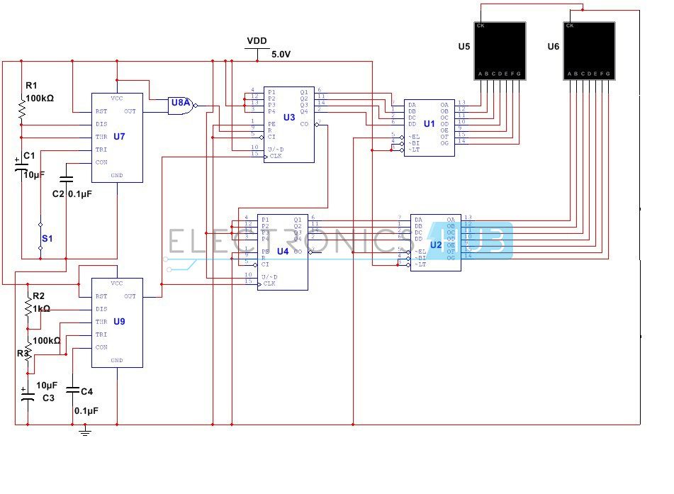
0 99 counter circuit diagram decade counter bcd counter electronics hub, 2 digit object counter circuit diagram using ic 555 amp lm358, 0 99 counter circuit diagram download ebooks, mod 6 counter 0 ic 74161 all about circuits, 2 digit up down counter circuit using 7 segment displays, counters digital circuits worksheets, 0 99 counter by ic 4017 circuit diagram world, ring. 0 99 counter using avr microcontroller microcontrollers computer technology circuit diagram. 0 to 99 up counter with the help of cd4026 circuit diagram.
bmw fuse box diagram 06 5 series 1999 ford ranger 4 0 engine diagram wiring diagram schematic symbol 93 acura integra wiring diagram
0 60 Counter Circuit Diagram
Display the result using hex displays. I am using logic works 5 and i cannot get a the first hex to get a number to start the counter and i cannot figure out how to make it stop at 99, or 63 hex. Now we are going to a little deeper part and we will study its basic structure known as block diagram. 3 or 4 can be removed if desired number of digits.

Source: pinterest.com
3 or 4 can be removed if desired number of digits. If you want to display 3 digits, three displays should be used i.e. Display the result using hex displays. Now we are going to a little deeper part and we will study its basic structure known as block diagram. 0 99 counter circuit diagram complete a timing diagram for.

Source: pinterest.com
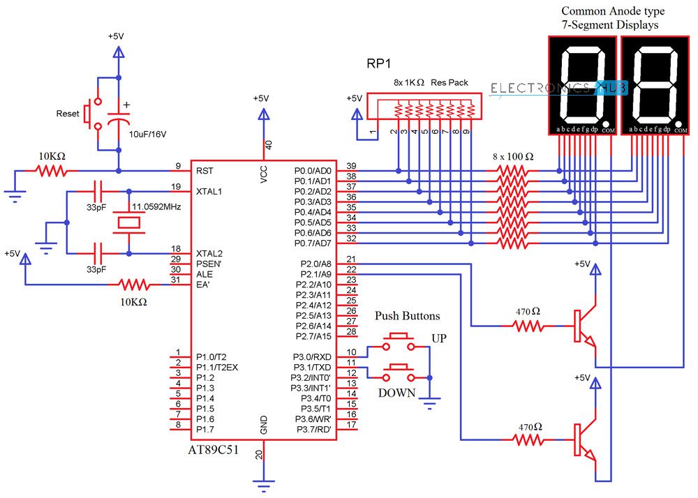
Pin 3 of both cd4026 ic is connected to positive supply (+vcc) which turns on the display. 7446 seven segment decoder driver circuit diagram componentes eletronicos esquemas eletronicos eletronica digital. There are many circuits available for 2 digit up/down counter but using a microcontroller reduces components and space on the board but simple programming. Connect the pin 3 of both.

Source: tianpinyt.blogspot.com
Its count always in the upward direction (in increasing order) that’s why it is also known as up counter. Note :draw a full circuit diagram for a designed counter. If pin 3 is connected to the ground we will get a blank display on 7 segment output. Driving a two digit common anode seven segment display using 74ls90 bcd decade.

Source: dsigngo.blogspot.com
Pin 15 which is the reset pin of cd4026 is connected to the ground so that when counting reaches 99, it resets the counter to zero. Code 7447 is used as a solvent. Please by assembly only assembly 0 99 counter using avr microcontroller microcontrollers computer technology circuit diagram. 0 99 7 segment display counter circuit circuit electronics circuit circuit.

Source: oguzyesilyurt.blogspot.com
0 99 counter circuit diagram complete a timing diagram for this synchronous counter circuit and identify the direction of its binary count think carefully about how you would choose to build and package your four bit cascadable counters and then draw a schematic diagram q 0 of the left counter is the lsb and q 3 of the right Ic1.

Source: forum.allaboutcircuits.com
Because its counting sequence is 0,1,2,3,4,5,6,7,8,9. Counter the forward / backward counters (74192) go over to the use of numbers missing or corrected immediately. The ic cd40333 is a 5 stage johnson. 0 99 counter using avr microcontroller microcontrollers computer technology circuit diagram. Driving a two digit common anode seven segment display using 74ls90 bcd decade counter 0 to 99.

Source: pinterest.de
If pin 3 is connected to the ground we will get a blank display on 7 segment output. Pin 15 which is the reset pin of cd4026 is connected to the ground so that when counting reaches 99, it resets the counter to zero. I am using logic works 5 and i cannot get a the first hex to get.

Source: dh-nx.com
Digital counter 0 to 999, driving a common anode seven segment display using 74ls90 bcd decade. And also connect the pin 15 which is a reset pin of the both the ic together so that when counting reaches to 99. Gallery for 4 digit up/down counter circuit diagram The msb is clocked by the reset pulse from the lsb counter.
")
Source: robocon.vn
Code 7447 is used as a solvent. Display the result using hex displays. If pin 3 is connected to the ground we will get a blank display on 7 segment output. Pin 3 of both cd4026 ic is connected to positive supply (+vcc) which turns on the display. Driving a two digit common anode seven segment display using 74ls90 bcd.

Source: wiringdiagramall.blogspot.com
Counter the forward / backward counters (74192) go over to the use of numbers missing or corrected immediately. There are many circuits available for 2 digit up/down counter but using a microcontroller reduces components and space on the board but simple programming. 0 99 7 segment display counter circuit circuit electronics circuit circuit diagram. 0 99 counter circuit diagram complete.

Source: electrical-engineering-world1.blogspot.com
7446 seven segment decoder driver circuit diagram componentes eletronicos esquemas eletronicos eletronica digital. Driving a two digit common anode seven segment display using 74ls90 bcd decade counter 0 to 99 seven segment display circuit diagram segmentation. Now we are going to a little deeper part and we will study its basic structure known as block diagram. Display the result using.

Source: dsigngo.blogspot.com
4 input nand gate truth table nand gate electronic circuit projects schmitt trigger The msb is clocked by the reset pulse from the lsb counter circuit. I am using logic works 5 and i cannot get a the first hex to get a number to start the counter and i cannot figure out how to make it stop at 99,.

Source: circuitdigest.com
If pin 3 is connected to the ground we will get a blank display on 7 segment output. Driving a two digit common anode seven segment display using 74ls90 bcd decade counter 0 to 99 seven segment display circuit diagram segmentation. Display the result using hex displays. If you want to display 3 digits, three displays should be used i.e..

Source: virtuaalivalonneulenurkkaus.blogspot.com
If pin 3 is connected to ground we will get a blank display on 7 segment output. Pin 15 which is the reset pin of cd4026 is connected to the ground so that when counting reaches 99, it resets the counter to zero. And also connect the pin 15 which is a reset pin of the both the ic together.

Source: tailieu8051.blogspot.com
Any help would be amazing. Ic1 is a unit counter ic. 4 input nand gate truth table nand gate electronic circuit projects schmitt trigger 3 or 4 can be removed if desired number of digits. This circuit can be used in conjunction with various circuits where a counter to display the progress adds some more attraction.

Source: engineersgarage.com
The ic cd40333 is a 5 stage johnson. 0 99 counter circuit diagram complete a timing diagram for this synchronous counter circuit and identify the direction of its binary count think carefully about how you would choose to build and package your four bit cascadable counters and then draw a schematic diagram q 0 of the left counter is the.

Source: oguzyesilyurt.blogspot.com
If pin 3 is connected to the ground we will get a blank display on 7 segment output. Gallery for 4 digit up/down counter circuit diagram 0 99 counter using avr microcontroller microcontrollers computer technology circuit diagram. Connect the pin 3 of both the ic 1 and 2 to supply, to on the display. Code 7447 is used as a.

Source: pinterest.com
Its count always in the upward direction (in increasing order) that’s why it is also known as up counter. Here is the circuit diagram of a seven segment counter based on the counter ic cd 4033. 0 99 counter circuit diagram complete a timing diagram for this synchronous counter circuit and identify the direction of its binary count think carefully.

Source: circuitsan.blogspot.com
I am using logic works 5 and i cannot get a the first hex to get a number to start the counter and i cannot figure out how to make it stop at 99, or 63 hex. And also connect the pin 15 which is a reset pin of the both the ic together so that when counting reaches to.

Source: subjecteee.blogspot.com
And also connect the pin 15 which is a reset pin of the both the ic together so that when counting reaches to 99. 0 99 7 segment display counter circuit circuit electronics circuit circuit diagram. If you want to display 3 digits, three displays should be used i.e. Ics 7490 decade counter is an example of a sequential circuit..